MyLibreLab User Documentation and Tutorials
Abstract:
MyLibreLab software is a visual programming environment, especially to control and communicate with microcontrollers (MCU) and microprocessors. Using blocks, which carry specific functionality and connections, the user can implement an algorithm. The software includes elements to communicate with the commonly used MCU development/expansion boards and single-board computers, such as Arduino®, Raspberry Pi®, and Android™ devices. MyLibreLab can be considered as a Free, Libre, And Open Source Software (FLOSS) alternative to National Instrument™'s LabVIEW™. The user can design graphical user interfaces (GUI) to control electronic hardware through serial communication (USB UART).
MyLibreLab is a hard fork of the parent project MyOpenLab with the specific goals of reviving the international community, as well as using modern development practices and tools. The MyOpenLab project was initiated by Carmelo Daniel Salafia, a German developer, in 2006. In 2017, the development was handed over to Robinson Javier Velásquez, a Spanish developer.
The MyLibreLab code base has a licence of The GNU General Public License v3.0 and this documentation is licenced as Creative Commons BY-NC-SA.
If you have just started learning the software please read the FAQ section first and then follow the Tutorials.
Community:
There are several ways you can get in touch with the community. If you have questions you are encouraged to ask them via GitHub issues using the tag [Question] at the beginning of the title and post the link to the Discord group. If you want to stay in touch with the community install the Discord app on your computer or mobile phone. Alternatively, you may use the ##MyOpenLab or #MyOpenLab IRC channels on Freenode, post questions on MyOpenLab Forum or its SourceForge issues.
Before asking new questions please consult the internet using search engines (e.g., Google) to be sure that it hasn’t been asked before. Duplicate questions are not appreciated.
Installation:
MyLibreLab is a Java program so basically, you should be able to download the latest version and run it on all Operating Systems (OS) such as GNU/Linux, macOS, and Windows. But we highly recommend that you use a package manager.
-
Windows: On Windows OS please use Chocolatey package manager:
choco install mylibrelab
-
macOS: On macOS please use HomeBrew Cask package:
brew cask install mylibrelab
-
GNU/Linux: using AppImage…?
FAQ:
-
Who is this software for? MyLibreLab is a software for students, educators, and makers who want to do visual programming and hardware communication (i.e., serial UART).
-
Is it a complete LabVIEW alternative? Not at all. LabVIEW is an expensive proprietary software designed and maintained by a big group of developers at National Instrument for the last couple of decades. MyLibreLab is a community-driven project maintained by volunteers. You can not open LabVIEW files in MyLibreLab or vice versa.
Tutorials:
Example 1: Blinking LED
This example is inspired by the post "easy GUI front ends for Arduino Raspberry pi, and more with MyOpenLab" by Al Williams (Twitter, LinkedIn) published on hackaday.com. In this example you will build a bench tool by creating a "VirtualMachine (VM)" (i.e., virtual interfaces in MyLibreLab/MyOpenLab lingo). The VM will use your computer as a control panel and readout, and the electronic hardware as the physical interface. The MyLibreLab VM consists of two parts, like LabVIEW programs, a front end panel GUI and a block diagram program. some components of the block diagram will be also on the front panel such as switches, LEDs. While, some components only live on the block diagram side of the VM. On the block diagram panel you can connect components together to implement a computational algorithm or represent signal flow to physical systems such as Arduino and Raspberry Pi I/O.
To follow along this tutorial you need the hardware mentioned in this arduino.cc tutorial and a USB connection to the computer. Alternatively If you don’t have access to the actual hardware you may use software Like SimulIDE and KTechLab to emulate the hardware and have virtual serial ports. (#todo)
Installing Firmata:
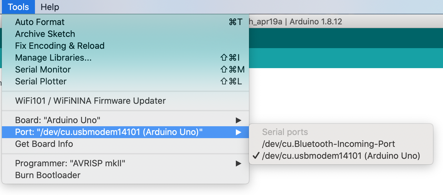
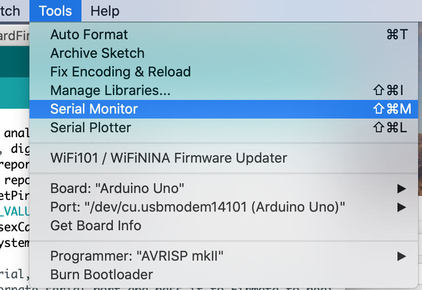
Firmata library provides a standard protocol for serial communication and control of an Arduino expansion board. Connect the Arduino Uno board to the computer via USB cable, and open the Arduino IDE. Make sure you have the right port and board selected from the Menu bar > Tools:
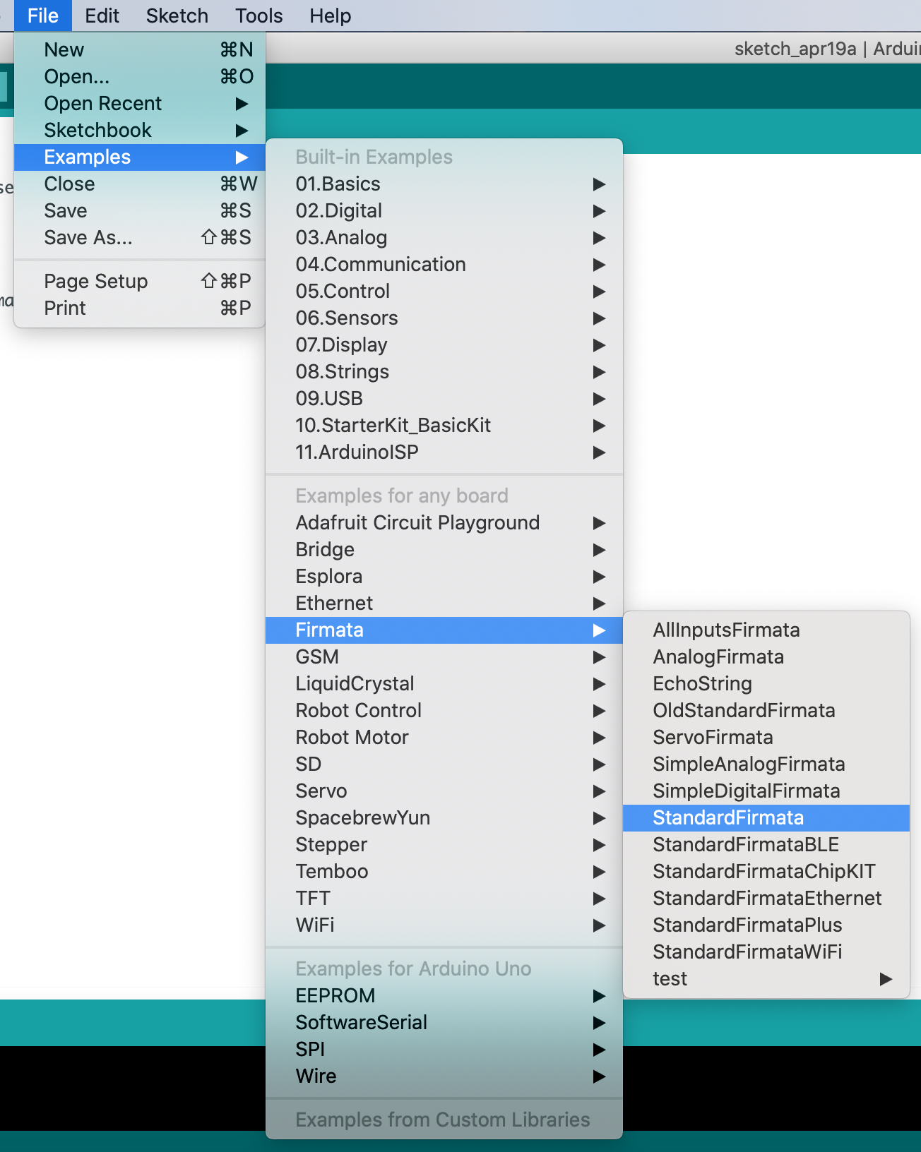
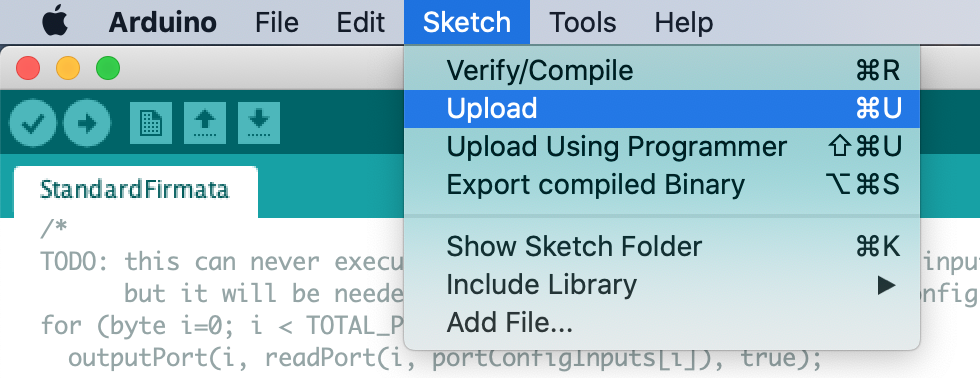
Select the standardFirmata sketch from Menu bar > File > Examples > Firmata > StandardFirmata
and add the line below as the first line of the setup function:
analogReference(INTERNAL);
or alternatively upload the standardFirmata/StandardFirmata.ino sketch in this tutorial to the Arduino board.
To test that everything is working properly, open the Menu bar > Tools > Serial Monitor
and make sure the Baud rate of 57600 is selected at the bottom right corner
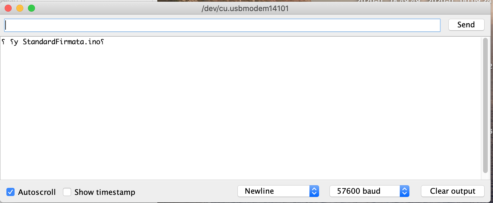
you should see the above message in the terminal.
Creating the MyLibreLab project:
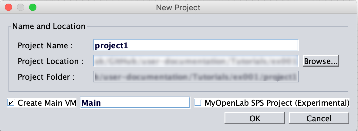
Open the MyLibreLab software and create a new project from the toolbar or the menu bar (Alt⌥+a).
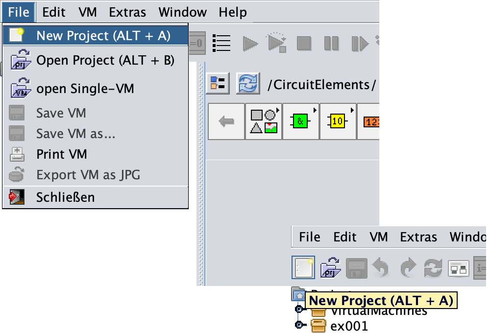
by specifying the Project Name, Project Location, and name of the Main VM and select OK:
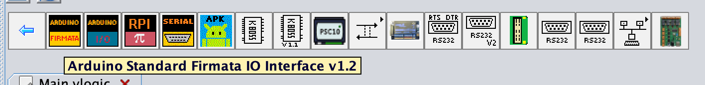
then from the menu bar select the Interfaces:

and consequently select the Arduino Standard Firmata Interface …
and place it on the Circuit Panel:
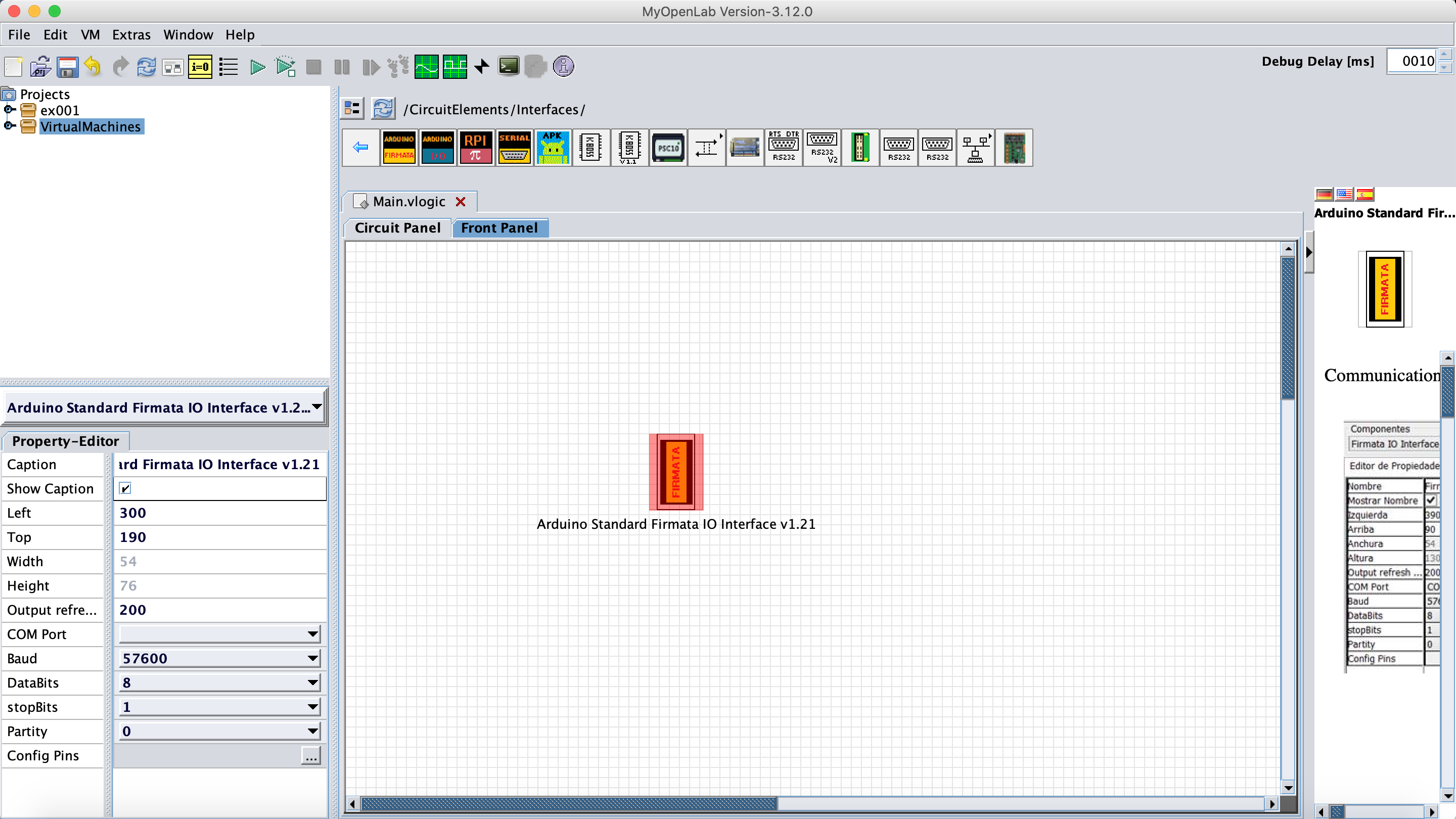
while the Firmata block is selected, on the Property-Editor panel, choose the right COM Port:
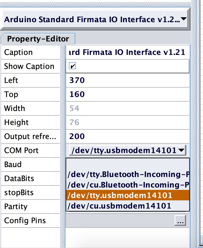
and then select the … on the Config Pins row.
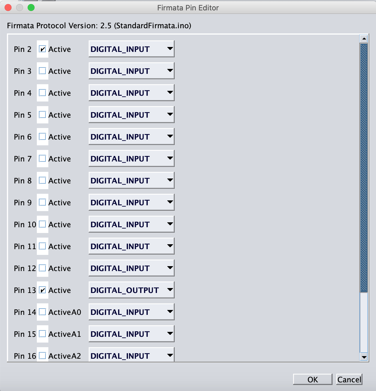
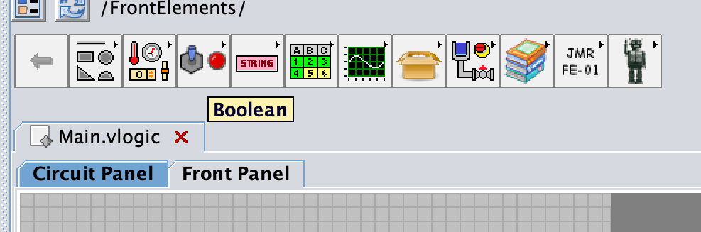
activate Pin 2 as DIGITAL_INPUT and Pin 13 as DIGITAL_OUTPUT. Go to the Front panel and then select the Boolean:
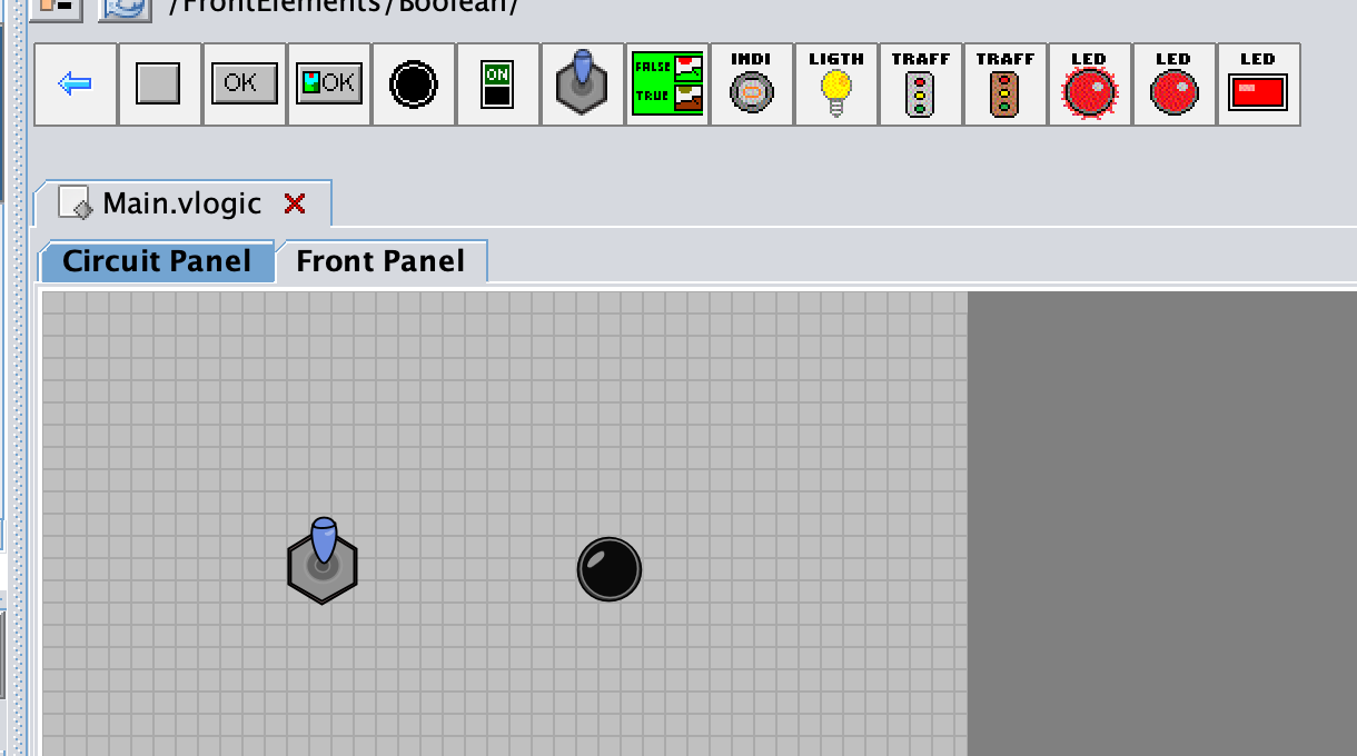
put an Tilt button and LED red on the Front Panel:
now go back to the Circuit panel and connect the switch to Pin 2 and the Pin 13 to the LED
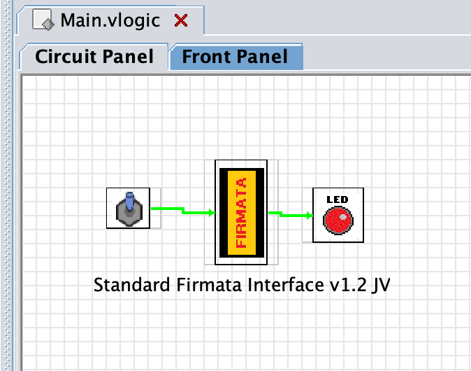
and then run: